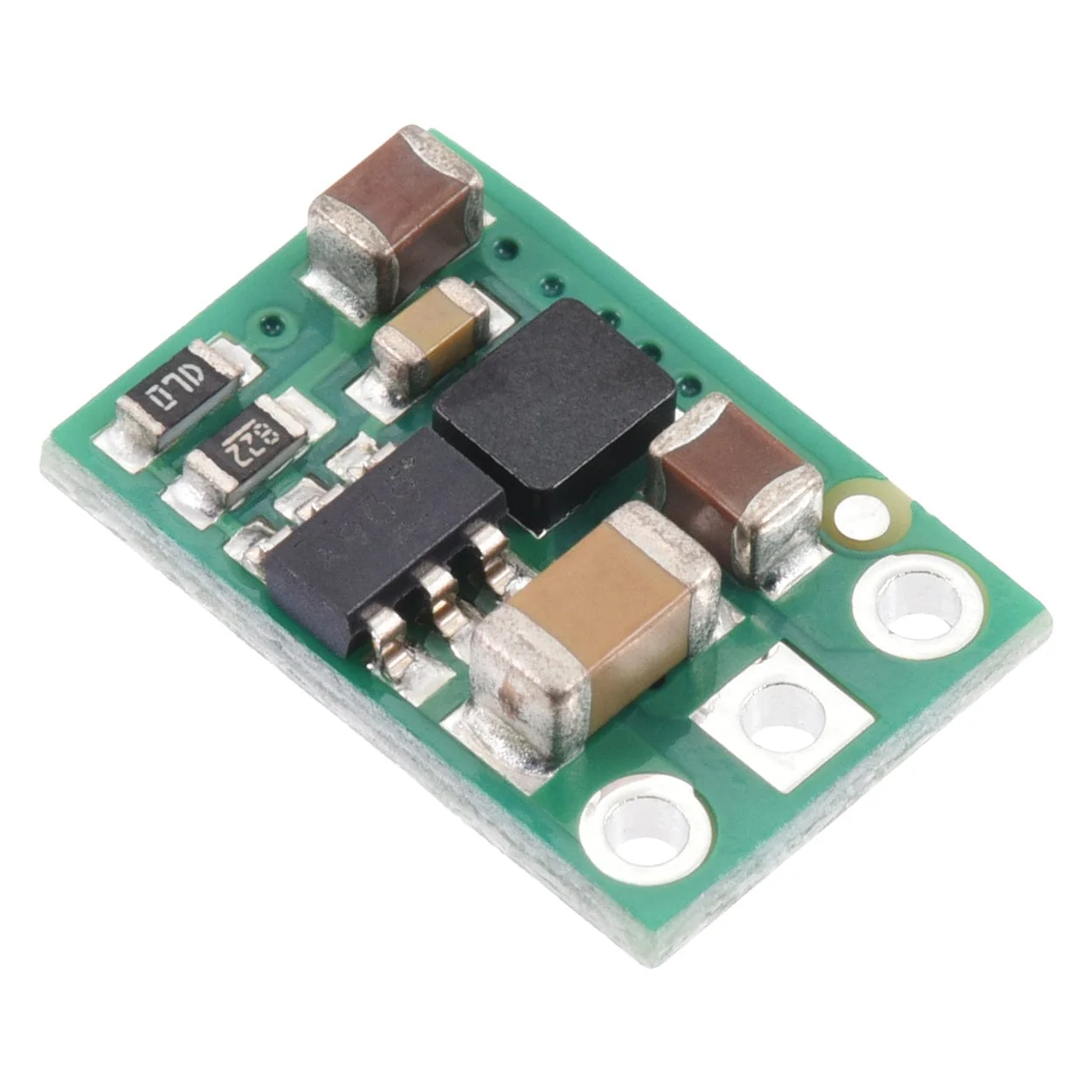
Pololu 12V 500mA Step-Down Voltage Regulator (D45V5F12)
The Pololu D45V5F12 is a compact 12V step-down voltage regulator that efficiently converts an input voltage from 12.5V to 65V into a stable 12V output, supporting continuous currents up to 500mA.
The D45V5Fx family of synchronous buck (step-down) voltage regulators generate lower voltages from input voltages as high as 65V while supporting maximum continuous output currents between 400mA and 700mA, depending on the combination of input and output voltage.
They are switching regulators (also called switched-mode power supplies (SMPS) or DC-to-DC converters), which makes them much more efficient than linear voltage regulators, especially when the difference between the input and output voltage is large.
The regulators feature short-circuit protection and thermal shutdown protection, which helps prevent damage from overheating. The boards do not have reverse voltage protection.
This item is the D45V5F12, which outputs a fixed 12V.
Features
- Input voltage: 12.5V to 65V (minimum input subject to dropout voltage considerations; see the dropout voltage section for details)
- Output voltage: 12V with 4% accuracy
- Maximum output current: 700 mA (see the maximum continuous output current graph below)
- Fixed 1.1 MHz switching frequency for normal loads (frequency is reduced at light loads to increase efficiency)
- Low quiescent current: < 0.2 mA for most of the operating range (see the quiescent current graph below)
- Short-circuit and over-temperature protection
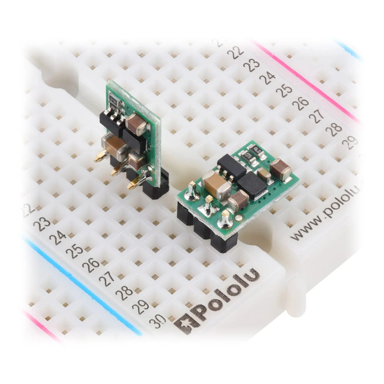
- Small size: 7.6mm × 11.4mm × 2.8mm
- Weight: 0.4g
Specifications
- Minimum operating voltage: 12.5V
- Maximum operating voltage: 65V
- Maximum output current: 550mA
- Output voltage: 12V
- Reverse voltage protection?: N
- Maximum quiescent current: 4mA
- Output type: fixed 12V
Resources
Links
- Dimension diagrams
- 3D Model
- Drill Guide
- Understanding Destructive LC Voltage Spikes
Connections

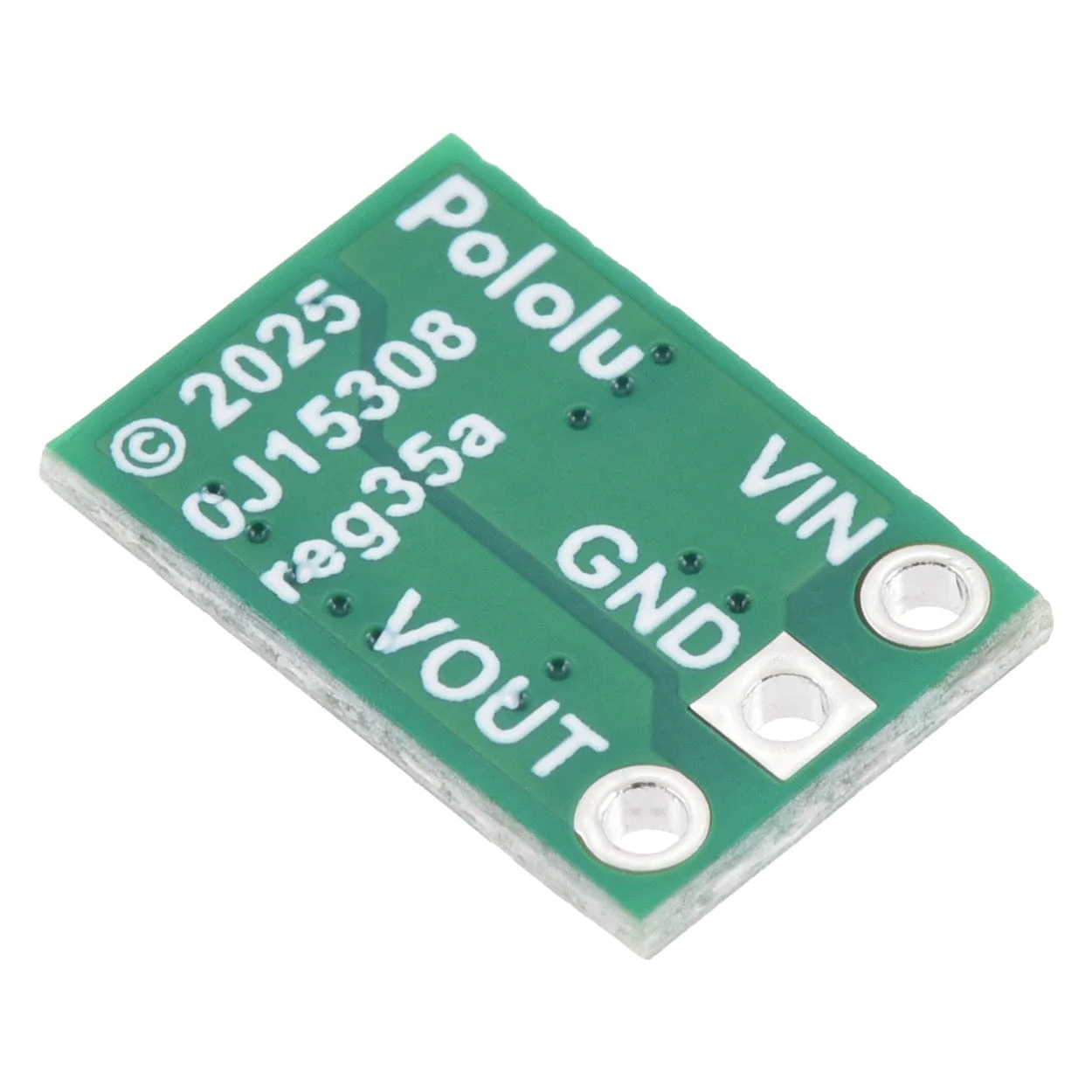
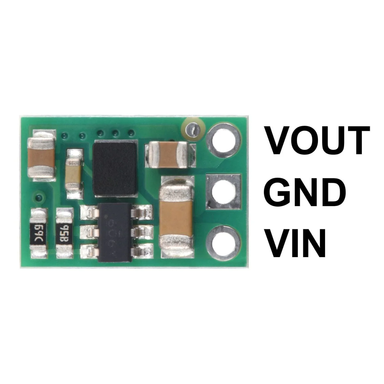
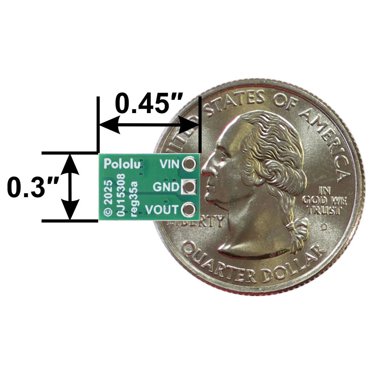
This regulator has three connections: input voltage (VIN), ground (GND), and output voltage (VOUT).
The input voltage, VIN, powers the regulator. Voltages between 4V and 65V can be applied to VIN, but generally the effective lower limit of VIN is VOUT plus the regulator’s dropout voltage, which varies approximately linearly with the load (see below for graphs of the dropout voltage as a function of the load). Additionally, please be wary of destructive LC spikes (see below for more information).
VOUT is the regulated output voltage.
The three connections are labelled on the back side of the PCB and are arranged with a 0.1″ spacing along the edge of the board for compatibility with solderless breadboards, connectors, and other prototyping arrangements that use a 0.1″ grid. You can solder wires or 0.1″ header pins directly to the board. Note: header pins are not included with this product, but straight male header strips and right-angle male header strip are available separately.
Typical efficiency
The efficiency of a voltage regulator, defined as (Power out)/(Power in), is an important measure of its performance, especially when battery life or heat are concerns.

Maximum continuous output current
The maximum achievable output current of these regulators varies with the input voltage but also depends on other factors, including the ambient temperature, air flow, and heat sinking.
The graph below shows maximum output currents that these regulators can deliver continuously at room temperature in still air and without additional heat sinking.

Quiescent current
The quiescent current is the current the regulator uses just to power itself, and the graph below shows this for the different regulator versions as a function of the input voltage.

Typical dropout voltage
The dropout voltage of a step-down regulator is the minimum amount by which the input voltage must exceed the regulator’s target output voltage in order to ensure the target output can be achieved.
For example, if a 5 V regulator has a 1 V dropout voltage, the input must be at least 6 V to ensure the output is the full 5 V. Generally speaking, the dropout voltage increases as the output current increases. The graph below shows the dropout voltages for the different members of this regulator family:

LC voltage spikes
When connecting voltage to electronic circuits, the initial rush of current can cause voltage spikes that are much higher than the input voltage. If these spikes exceed the regulator’s maximum voltage (65 V), the regulator can be destroyed. In our tests with typical power leads (36″/1m test clips), we observed spikes approaching 65 V at input voltages around 30 V.
If you are connecting more than 30 V or your power leads or supply has high inductance, we recommend soldering a suitably rated 33 μF or larger electrolytic capacitor close to the regulator between VIN and GND.
More information about LC spikes can be found in our application note, Understanding Destructive LC Voltage Spikes.
Product Information
Product Information
Shipping & Returns
Shipping & Returns
Description
The Pololu D45V5F12 is a compact 12V step-down voltage regulator that efficiently converts an input voltage from 12.5V to 65V into a stable 12V output, supporting continuous currents up to 500mA.
The D45V5Fx family of synchronous buck (step-down) voltage regulators generate lower voltages from input voltages as high as 65V while supporting maximum continuous output currents between 400mA and 700mA, depending on the combination of input and output voltage.
They are switching regulators (also called switched-mode power supplies (SMPS) or DC-to-DC converters), which makes them much more efficient than linear voltage regulators, especially when the difference between the input and output voltage is large.
The regulators feature short-circuit protection and thermal shutdown protection, which helps prevent damage from overheating. The boards do not have reverse voltage protection.
This item is the D45V5F12, which outputs a fixed 12V.
Features
- Input voltage: 12.5V to 65V (minimum input subject to dropout voltage considerations; see the dropout voltage section for details)
- Output voltage: 12V with 4% accuracy
- Maximum output current: 700 mA (see the maximum continuous output current graph below)
- Fixed 1.1 MHz switching frequency for normal loads (frequency is reduced at light loads to increase efficiency)
- Low quiescent current: < 0.2 mA for most of the operating range (see the quiescent current graph below)
- Short-circuit and over-temperature protection
- Small size: 7.6mm × 11.4mm × 2.8mm
- Weight: 0.4g
Specifications
- Minimum operating voltage: 12.5V
- Maximum operating voltage: 65V
- Maximum output current: 550mA
- Output voltage: 12V
- Reverse voltage protection?: N
- Maximum quiescent current: 4mA
- Output type: fixed 12V
Resources
Links
- Dimension diagrams
- 3D Model
- Drill Guide
- Understanding Destructive LC Voltage Spikes
Connections
This regulator has three connections: input voltage (VIN), ground (GND), and output voltage (VOUT).
The input voltage, VIN, powers the regulator. Voltages between 4V and 65V can be applied to VIN, but generally the effective lower limit of VIN is VOUT plus the regulator’s dropout voltage, which varies approximately linearly with the load (see below for graphs of the dropout voltage as a function of the load). Additionally, please be wary of destructive LC spikes (see below for more information).
VOUT is the regulated output voltage.
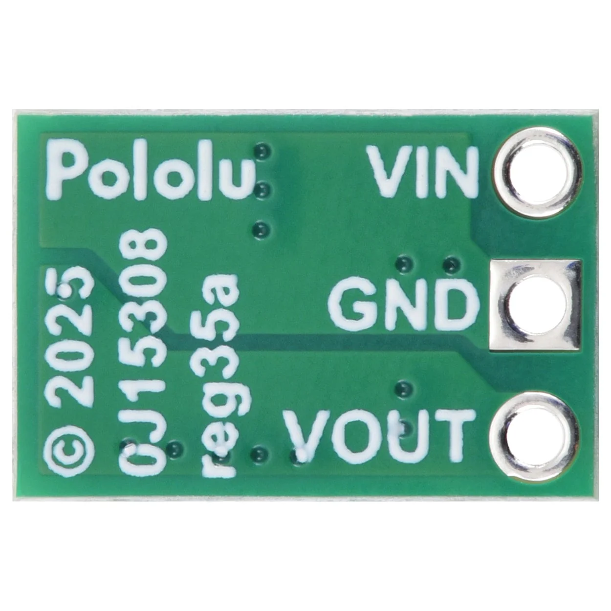
The three connections are labelled on the back side of the PCB and are arranged with a 0.1″ spacing along the edge of the board for compatibility with solderless breadboards, connectors, and other prototyping arrangements that use a 0.1″ grid. You can solder wires or 0.1″ header pins directly to the board. Note: header pins are not included with this product, but straight male header strips and right-angle male header strip are available separately.
Typical efficiency
The efficiency of a voltage regulator, defined as (Power out)/(Power in), is an important measure of its performance, especially when battery life or heat are concerns.
Maximum continuous output current
The maximum achievable output current of these regulators varies with the input voltage but also depends on other factors, including the ambient temperature, air flow, and heat sinking.
The graph below shows maximum output currents that these regulators can deliver continuously at room temperature in still air and without additional heat sinking.
Quiescent current
The quiescent current is the current the regulator uses just to power itself, and the graph below shows this for the different regulator versions as a function of the input voltage.
Typical dropout voltage
The dropout voltage of a step-down regulator is the minimum amount by which the input voltage must exceed the regulator’s target output voltage in order to ensure the target output can be achieved.
For example, if a 5 V regulator has a 1 V dropout voltage, the input must be at least 6 V to ensure the output is the full 5 V. Generally speaking, the dropout voltage increases as the output current increases. The graph below shows the dropout voltages for the different members of this regulator family:
LC voltage spikes
When connecting voltage to electronic circuits, the initial rush of current can cause voltage spikes that are much higher than the input voltage. If these spikes exceed the regulator’s maximum voltage (65 V), the regulator can be destroyed. In our tests with typical power leads (36″/1m test clips), we observed spikes approaching 65 V at input voltages around 30 V.
If you are connecting more than 30 V or your power leads or supply has high inductance, we recommend soldering a suitably rated 33 μF or larger electrolytic capacitor close to the regulator between VIN and GND.
More information about LC spikes can be found in our application note, Understanding Destructive LC Voltage Spikes.