Industrial IoT Wireless Expansion Module for Raspberry Pi CM4
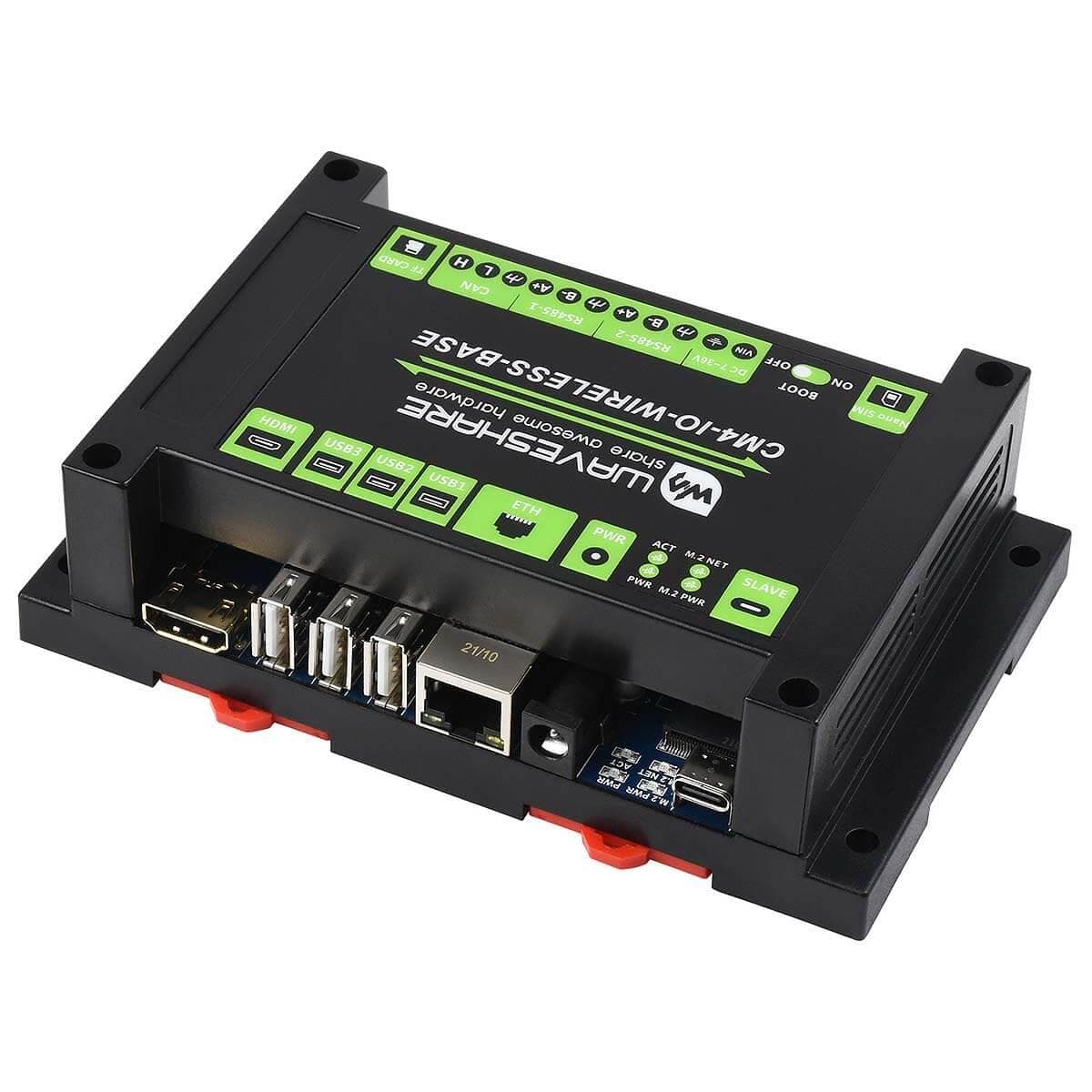
This is an industrial expansion module for the Raspberry Pi Compute Module 4 (not included), which features common interfaces such as Gigabit Ethernet, HDMI, USB, CSI and GPIO. The expansion also allows additional 4G / 5G / LoRa wireless communication modules (not included) to be connected via the M.2 or Mini-PCIe socket and sim card slot. There are also industrial interfaces including RS485, CAN and an onboard RTC.
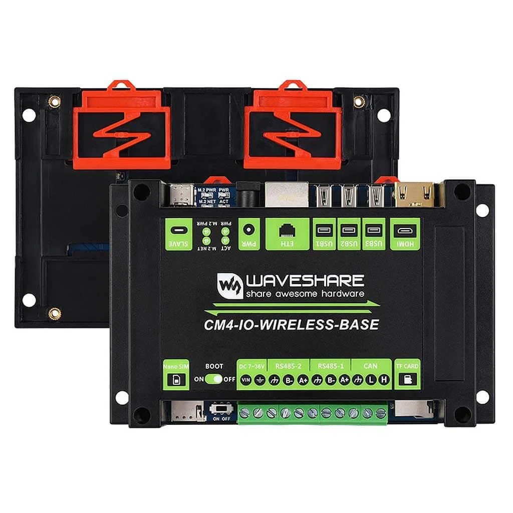
Combined with the industrial rail-mount protection case, the module is an ideal choice for building an IoT gateway, 4G/5G router, IoT data acquisition, or even a PLC device in an industrial automatic control system and more!
Expansion base only. Does not include the CM4, power supply or M.2 B-Key LTE/LoRa module. We have stocked this base-only version to allow you to choose your wireless and power options separately.

Important Notes
- DO NOT hot-plug any devices except the USB and HDMI
- Please check the fan voltage before connecting the cooling fan. The board supports a 12V cooling fan by default, if you want to use a 5V cooling fan, please change the FAN_VCC resistor
- DO NOT connect other devices while writing CM4 via Type C interface
- 5V/2.5A or higher power supply is recommended
- DO NOT power the board by 12V DC and the 5V Type C at the same time
- The USB2.0 is disabled by default, you need to add the line dtoverlay=dwc2,dr_mode=host to config.txt to enable it.
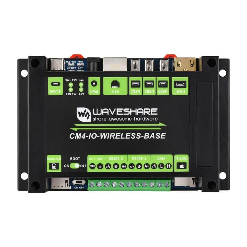
What's Onboard?

1) CM4 socket
- Suitable for all variants of Compute Module 4
2) HDMI connector
- Supports 4K 30fps output
3) USB 2.0 ports
- 3x USB 2.0, for connecting sorts of USB devices
4) RJ45 Gigabit Ethernet
- 10/100/1000M compatible
5) DC power supply
- 7 ~ 36V DC input
6) CM4 status indicator
- PWR: Raspberry Pi power indicator
- ACT: Raspberry Pi operating status indicator
7) 4G/5G module status indicator
- M.2 PWR: module enable indicator
- M.2 NET: module operating status indicator
8) PWR & USB
- 5V DC power supply or USB programming port
9) M.2 B KEY
- Supports 4G/5G modules, or other communication modules using USB channel
10) Nano-SIM card slot
- Supports standard Nano-SIM card for 5G/4G/3G/2G communication
11) BOOT selection
- ON: CM4 will be booted from USB-C interface
- OFF: CM4 will be booted from eMMC or Micro SD card
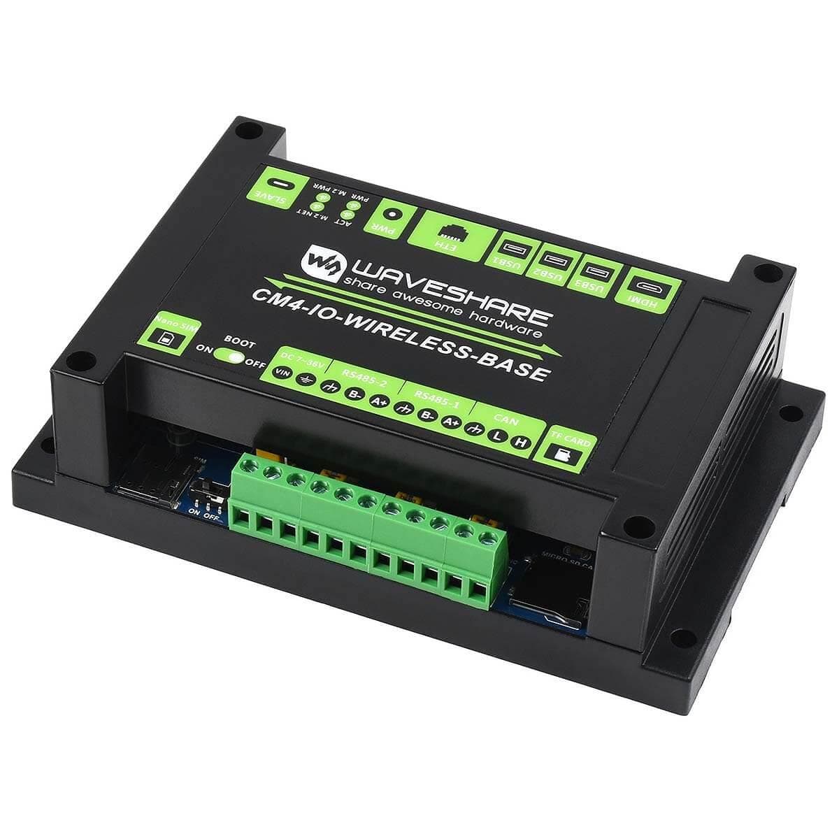
12) DC power supply
- 7 ~ 36V DC input
13) Dual non-isolated RS485
- 2x RS485, with 600W lightning proof, anti-surge, and 15KV ESD protection (reserved 120R optional balancing resistor jumper)
14) Non-isolated CAN
- ESD protection and transient spike voltage protection (reserved 120R optional balancing resistor jumper)
15) Micro SD card slot
- For connecting a Micro SD card with a pre-burnt image (Lite variant ONLY)
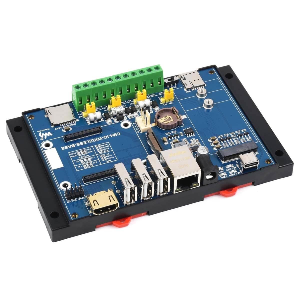
16) Fan header
- For connecting a cooling fan, allows speed adjustment and measurement
17) Camera port
- MIPI CSI camera port, 15Pin 1mm pitch
18) RTC battery holder
- Supports CR1220 button cell
19) M.2 VCC selection
- Select 3.3V or 4.2V power supply
20) RTC interruption configuration
- PI-RUN: CM4 will reboot on RTC interruption
- GL-EN: CM4 powerdown on RTC interruption
- D17: D17 pin is triggered on RTC interruption (default)
21) IO-VREF selection
- Set the CM4 IO logic level as 3.3V (default) or 1.8V
22) FAN power supply selection
- Select 12V (default) or 5V power to drive the fan
23) System function configuration
- BT_DIS: Bluetooth disabled, for CM4 with antenna variant ONLY
- WiFi_DIS: WiFi disabled, for CM4 with antenna variant ONLY
- WP_DIS: boot mode switch, ONLY be used when NOT booted from eMMC or SD card
24) RTC/FAN I2C bus selection
- SDA0/SCL0: I2C-10 is shared with CSI/DSI (default)
- GPIO3/2: I2C-1 is shared with GPIO header
25) Partial GPIO header
- Including 1x I2C, 2x GPIO pins, and power supply
Specification
| CM4 Socket | suitable for all variants of Compute Module 4 |
| Networking | Gigabit Ethernet RJ45 M.2 B KEY / Mini-PCIe (via adapter) for connecting 5G/4G/LoRa module Nano-SIM card slot, supports Nano-SIM card for 5G/4G/3G/2G |
| USB | USB 2.0 × 3 |
| Pin Header | Non-isolated RS485 × 2, Non-isolated CAN × 1, Partial GPIO pins |
| Camera | MIPI CSI-2 × 1 (15pin 1.0mm FPC connector) |
| Video | HDMI × 1, supports 4K 30fps output |
| RTC | Real-time clock with battery socket and ability to wake CM4 |
| Storage | MicroSD card socket for Compute Module 4 Lite (without eMMC) variants |
| Fan Header | 5V/12V, allows speed adjustment and measurement |
| Power Input | 5V USB-C or 7~36V Barrel Jack (centre-positive) |
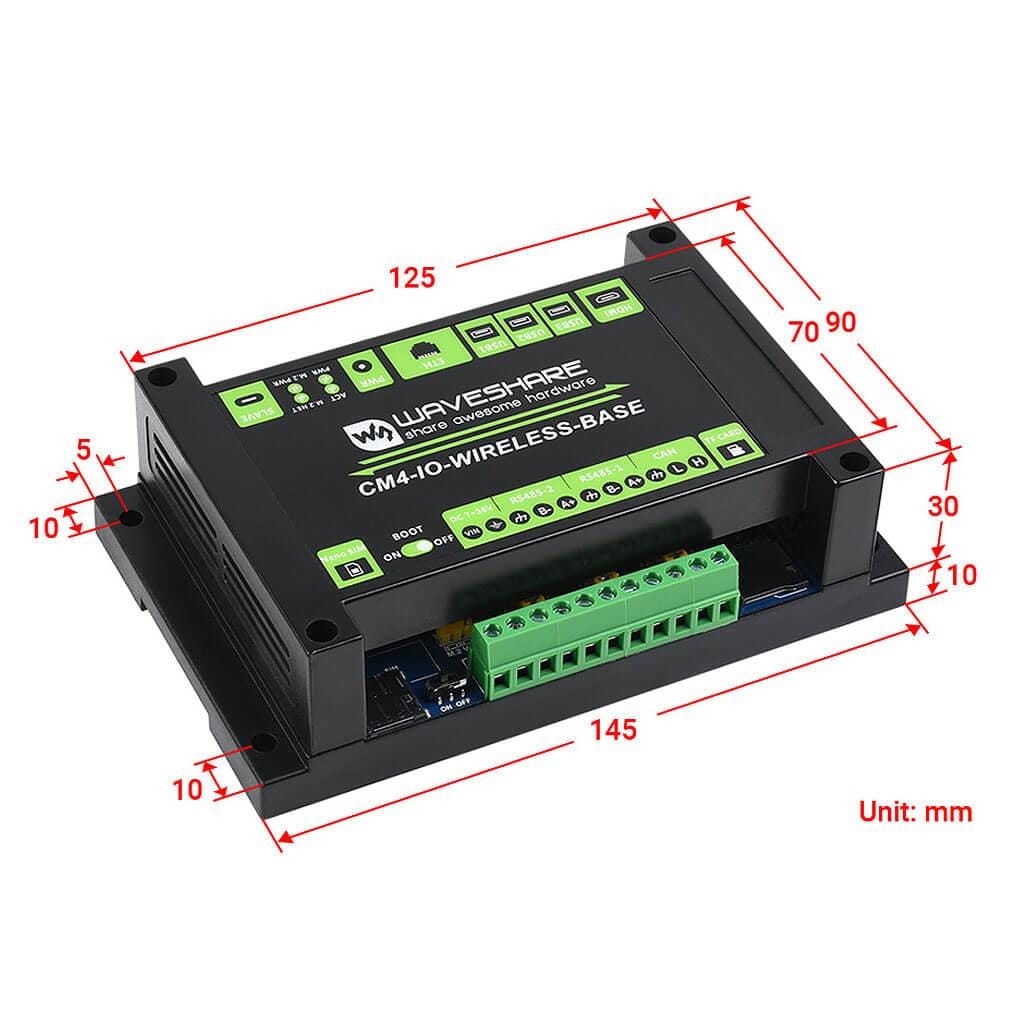
| Dimensions | 145 × 90 × 40mm |
Package Contents
- 1x CM4 IoT Wireless Base
- 1x PCIe to 4G/LoRa adapter
- 1x Screwdriver
- 1x Screws pack
You will also need
- A power supply (5V USB-C or 7-36V centre-positive barrel jack)
- Optional for wireless options: LTE/LoRa Module (M.2 B Key)/Sim card
Resources
- Product Wiki
Original: $65.36
-70%$65.36
$19.61Product Information
Product Information
Shipping & Returns
Shipping & Returns
Description
This is an industrial expansion module for the Raspberry Pi Compute Module 4 (not included), which features common interfaces such as Gigabit Ethernet, HDMI, USB, CSI and GPIO. The expansion also allows additional 4G / 5G / LoRa wireless communication modules (not included) to be connected via the M.2 or Mini-PCIe socket and sim card slot. There are also industrial interfaces including RS485, CAN and an onboard RTC.
Combined with the industrial rail-mount protection case, the module is an ideal choice for building an IoT gateway, 4G/5G router, IoT data acquisition, or even a PLC device in an industrial automatic control system and more!
Expansion base only. Does not include the CM4, power supply or M.2 B-Key LTE/LoRa module. We have stocked this base-only version to allow you to choose your wireless and power options separately.
Important Notes
- DO NOT hot-plug any devices except the USB and HDMI
- Please check the fan voltage before connecting the cooling fan. The board supports a 12V cooling fan by default, if you want to use a 5V cooling fan, please change the FAN_VCC resistor
- DO NOT connect other devices while writing CM4 via Type C interface
- 5V/2.5A or higher power supply is recommended
- DO NOT power the board by 12V DC and the 5V Type C at the same time
- The USB2.0 is disabled by default, you need to add the line dtoverlay=dwc2,dr_mode=host to config.txt to enable it.
What's Onboard?
1) CM4 socket
- Suitable for all variants of Compute Module 4
2) HDMI connector
- Supports 4K 30fps output
3) USB 2.0 ports
- 3x USB 2.0, for connecting sorts of USB devices
4) RJ45 Gigabit Ethernet
- 10/100/1000M compatible
5) DC power supply
- 7 ~ 36V DC input
6) CM4 status indicator
- PWR: Raspberry Pi power indicator
- ACT: Raspberry Pi operating status indicator
7) 4G/5G module status indicator
- M.2 PWR: module enable indicator
- M.2 NET: module operating status indicator
8) PWR & USB
- 5V DC power supply or USB programming port
9) M.2 B KEY
- Supports 4G/5G modules, or other communication modules using USB channel
10) Nano-SIM card slot
- Supports standard Nano-SIM card for 5G/4G/3G/2G communication
11) BOOT selection
- ON: CM4 will be booted from USB-C interface
- OFF: CM4 will be booted from eMMC or Micro SD card
12) DC power supply
- 7 ~ 36V DC input
13) Dual non-isolated RS485
- 2x RS485, with 600W lightning proof, anti-surge, and 15KV ESD protection (reserved 120R optional balancing resistor jumper)
14) Non-isolated CAN
- ESD protection and transient spike voltage protection (reserved 120R optional balancing resistor jumper)
15) Micro SD card slot
- For connecting a Micro SD card with a pre-burnt image (Lite variant ONLY)
16) Fan header
- For connecting a cooling fan, allows speed adjustment and measurement
17) Camera port
- MIPI CSI camera port, 15Pin 1mm pitch
18) RTC battery holder
- Supports CR1220 button cell
19) M.2 VCC selection
- Select 3.3V or 4.2V power supply
20) RTC interruption configuration
- PI-RUN: CM4 will reboot on RTC interruption
- GL-EN: CM4 powerdown on RTC interruption
- D17: D17 pin is triggered on RTC interruption (default)
21) IO-VREF selection
- Set the CM4 IO logic level as 3.3V (default) or 1.8V
22) FAN power supply selection
- Select 12V (default) or 5V power to drive the fan
23) System function configuration
- BT_DIS: Bluetooth disabled, for CM4 with antenna variant ONLY
- WiFi_DIS: WiFi disabled, for CM4 with antenna variant ONLY
- WP_DIS: boot mode switch, ONLY be used when NOT booted from eMMC or SD card
24) RTC/FAN I2C bus selection
- SDA0/SCL0: I2C-10 is shared with CSI/DSI (default)
- GPIO3/2: I2C-1 is shared with GPIO header
25) Partial GPIO header
- Including 1x I2C, 2x GPIO pins, and power supply
Specification
| CM4 Socket | suitable for all variants of Compute Module 4 |
| Networking | Gigabit Ethernet RJ45 M.2 B KEY / Mini-PCIe (via adapter) for connecting 5G/4G/LoRa module Nano-SIM card slot, supports Nano-SIM card for 5G/4G/3G/2G |
| USB | USB 2.0 × 3 |
| Pin Header | Non-isolated RS485 × 2, Non-isolated CAN × 1, Partial GPIO pins |
| Camera | MIPI CSI-2 × 1 (15pin 1.0mm FPC connector) |
| Video | HDMI × 1, supports 4K 30fps output |
| RTC | Real-time clock with battery socket and ability to wake CM4 |
| Storage | MicroSD card socket for Compute Module 4 Lite (without eMMC) variants |
| Fan Header | 5V/12V, allows speed adjustment and measurement |
| Power Input | 5V USB-C or 7~36V Barrel Jack (centre-positive) |
| Dimensions | 145 × 90 × 40mm |
Package Contents
- 1x CM4 IoT Wireless Base
- 1x PCIe to 4G/LoRa adapter
- 1x Screwdriver
- 1x Screws pack
You will also need
- A power supply (5V USB-C or 7-36V centre-positive barrel jack)
- Optional for wireless options: LTE/LoRa Module (M.2 B Key)/Sim card
Resources
- Product Wiki